





You have no products in your cart. Please visit our product catalog to add some products to your cart.
Browse ProductsMedia Center
ETI News
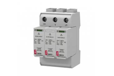
ETITEC M T2 DC: Surge Protection for battery storage systems
ETITEC M T2 DC product line is developed together with special ETI NH1 gBAT 200A/1500V DC fuses, and provides the best available Type 2 surge protection in battery storage systems. The devices ensure stable operation and protection against transient overvoltages in installations with high short-circuit capability and demanding operating conditions.
ETI Blog
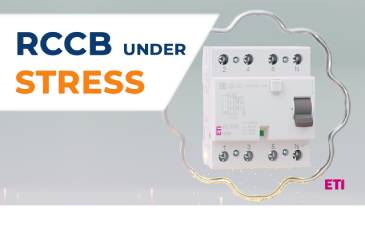
Electrodynamic Forces in RCCBs: How it Withstands Extreme Fault Conditions
During a short circuit, a residual current circuit breaker (RCCB) can experience forces strong enough to bend metal. These electrodynamic forces act within milliseconds, placing enormous mechanical stress on conductors, contacts, and structural components. Understanding how these forces arise—and how modern RCCB designs mitigate them—is essential for ensuring long-term reliability and electrical safety.
ETI News
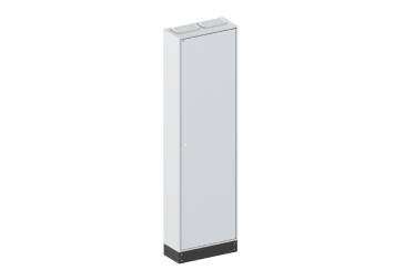
New LXN250 Enclosures Extend the SOLID GSX System
ETI is expanding the SOLID GSX system with the introduction of the LXN250 series – a new generation of modular enclosures designed to support flexible, scalable, and efficient switchboard construction.
ETI Blog
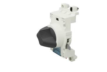
RO2S 250 Rotary Handle – Safer and Smarter Operation of EB2S 250 MCCBs
In low-voltage installations, safety and ease of operation go hand in hand. The right accessory can make daily handling simpler while also increasing protection during maintenance.
In our latest video, we present the RO2S 250 rotary handle, a breaker-mounted accessory designed specifically for ETI’s EB2S 250 moulded case circuit breaker (MCCB).
ETI News
EFI-2 & EFI-4 Type F RCCBs
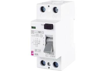
ETI introduces the EFI-2 and EFI-4 Type F residual current circuit breakers, designed for reliable protection in modern single-phase installations that include appliances with frequency inverters. Type F technology ensures safe operation even in the presence of mixed-frequency residual currents—a growing requirement in today’s households and small commercial environments.
ETI Corporate News
ETI at Light and Building 2026
We would like to welcome you at our stand at Light and Building 2026, which will take place from March 8th to 13th.
You can find us in Hall 11.0 / Stand C92.
ETI Blog
Compact Circuit Breakers – Understanding the Tripping Characteristics
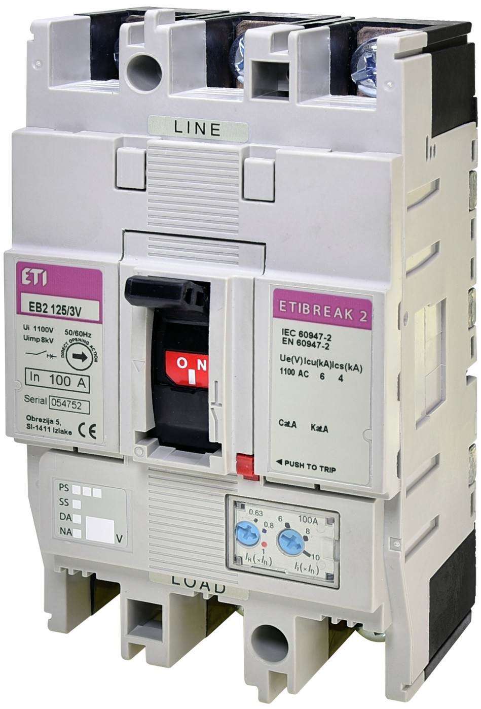
Low-voltage circuit breakers are used to protect low-voltage installations, cable lines, and connected equipment against overloads and short circuits. On the market, we encounter two different types of compact circuit breakers: those with thermo-magnetic (electromechanical) trip units and those with electronic trip units.
Thermo-magnetic compact circuit breakers operate based on a bimetal element and an electromagnetic trip mechanism. In the case of an overload current, due to the physical properties of the bimetal, it gradually bends until the circuit breaker trips. In the event of a short circuit, a strong magnetic force is generated, which activates the electromagnetic trip mechanism.
ETI News
Metal Distribution Boards DIDO MB – Built for Safety, Space, and Durability
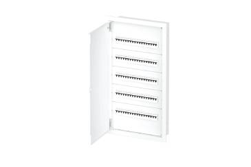
New DIDO MB series of metal distribution boxes, designed to ensure safe and reliable electrical distribution in both residential and commercial installations. The series is suitable for in-wall mounting in brick or hollow walls, making it a versatile choice for modern electrical installations.
ETI Blog
Selectivity of Protection with NH Fuse - Links
Selectivity of protective devices is a crucial factor to consider when designing low-voltage installations. The goal of selectivity is to minimize the impact of faults. When a fault occurs, only the affected part of the installation should be disconnected, while the rest of the system remains in operation.
Protection is considered selective—whether against short-circuits or overloads—if only the faulty section of the electrical installation is interrupted. This blog post first explains the difference between overloads and short-circuits and then explores how to ensure proper selective protection using NH fuse-links.
Overloads and Short-Circuits
An overload occurs when the current flowing through a conductor or cable exceeds its permissible continuous current-carrying capacity. This typically happens when too many devices are connected to the same circuit at once.
A short-circuit, on the other hand, occurs when two points of different potential in a circuit come into contact through a path of very low impedance, resulting in a sudden surge of current.
The size of short-circuit currents in low-voltage networks depends mainly on:
-
The supply transformer, including its inductive and resistive impedances
-
The impedance of cables and conductors between the transformer and the loads
Short-circuit currents are highest at the transformer terminals and decrease with distance along the distribution network. For example, the current at a main distribution board (RG) will be lower than at the transformer, and even lower at a downstream sub-distribution board (R).
In addition, three-phase short-circuits (L1–L2–L3) typically produce higher currents than single-phase short-circuits (L–N).
Picture 1: short-circuit in a low-voltage installation
I-t Characteristic of NH Fuse-Links
An NH fuse-link’s I-t characteristic (current-time characteristic), also known as the cut-off characteristic, defines the disconnection time as a function of the expected current.
For example, Figure 2 shows the I-t curves of two ETI NH-type gG fuse-links:
-
NH 50 A gG (blue, lower curve)
-
NH 80 A gG (green, upper curve)
If an overload current of 150 A occurs, the 50 A NH fuse-link disconnects in about 8 seconds, while the 80 A NH fuse-link disconnects in about 976 seconds.
This demonstrates how the lower-rated NH fuse-link reacts significantly faster.
Picture 2: I-t characteristics of NV 50 A gG and NV 80 A gG fuse-links
Selectivity in Overload Protection
Selectivity between NH fuse-links under overload conditions is evaluated using their I-t characteristics for operation times above 0.1 s.
Because this post focuses on overcurrent protection of cables and conductors, we’ll consider gG-type NH fuse-links, which are suitable for general use and protect circuits across the full current range.
In the example above, if two NH fuse-links rated 80 A and 50 A are connected in series and a current of 150 A flows:
-
The 50 A NH fuse-link disconnects in ~8 s
-
The 80 A NH fuse-link would disconnect in >900 s
The downstream (50 A) NH fuse-link has a lower-lying I-t curve and therefore operates faster, ensuring that only the fuse closest to the load disconnects. This guarantees selectivity under overload conditions.
Selectivity in Short-Circuit Protection
When dealing with very high overload or short-circuit currents, where disconnection occurs in less than 0.1 s, it is necessary to consider the pre-arcing energy (also known as the pre-arcing joule integral I²t) and the total (or operating joule integral) I²t of the NH fuse-links.
At extremely high fault currents, an NH fuse-link may disconnect in less than 5 ms—sometimes even during the first half-wave of the current. The energy passing through the fuse during this brief period is measured by the Joule integral (I²t).
-
Pre-arcing I²t: energy up to the point when the NH fuse-link element melts
-
Total I²t: energy up to the complete interruption of the current (including arc-extinction time)
For selectivity, the total I²t of the downstream (smaller) NH fuse-link must be lower than the pre-arcing I²t of the upstream (larger) NH fuse-link. Fuse manufacturers, including ETI, provide these values in their catalogs.
However, comparing I²t values can be complex for users and even for electrical professionals. Therefore, a practical rule applies:
For NH fuse-links of the same utilization category (e.g., gG) with rated currents ≥ 16 A, selectivity is ensured if the ratio of the upstream to downstream fuse ratings is at least 1.6 : 1.
This means the rated currents of two series-connected NH fuse-links must differ by at least two standard current steps.
For example:
-
With 80 A upstream and 50 A downstream, the ratio is 1.6, so selectivity is achieved.
-
If the upstream NH fuse-link were 63 A instead of 80 A, the ratio would be less than 1.6, and selectivity would have to be checked by comparing the I²t values.
Key Takeaways
-
Selectivity minimizes downtime and increases system safety by isolating only the faulty part of an installation.
-
Overload selectivity can be checked using the I-t curves: the downstream NH fuse-link must operate faster.
-
Short-circuit selectivity depends on the I²t energy values: the downstream NH fuse-link’s total I²t must be lower than the upstream NH fuse-link’s pre-arcing I²t.
-
As a rule of thumb, selectivity is guaranteed when the rated current ratio of the upstream to downstream NH fuse-links is ≥ 1.6 : 1.
By understanding these principles, installers and designers can improve the reliability and safety of low-voltage installations protected by NH fuse-links.
Table: comparison of the technical data of NV 50 A and NV 80 A fuse-links
Switch to Sustainable
Understanding Your Company’s Carbon Footprint
What is a carbon footprint?
A carbon footprint is the total amount of carbon dioxide (CO₂) and other greenhouse gases (GHGs) emitted by an activity, product, event, person, or organization. It is measured in tonnes of CO₂ equivalent (tCO₂e).
ETI News
KZS-1MS: Compact, Voltage-Independent Protection in One Module
The KZS-1MS is one of the first electromechanical (voltage-independent) residual current circuit breakers with overcurrent protection (RCBO) on the EN/IEC market available in only one modular width.
RCBOs combine residual current detection, short-circuit, and overload protection in a single device, providing both electric-shock protection and line protection. This all-in-one solution enhances reliability, improves system availability, and simplifies installation planning.
ETI Blog
KZS-1M-UNI: Compact Protection for Modern Electrical Installations
KZS-1M-UNI is a versatile solution for modern electrical installations. With the option to connect the electrical supply from either the top or the bottom, it provides greater flexibility and simplifies installation in various setups.
In the 1990s, a new type of protective device began appearing in electrical distribution boards in Slovenia – the so-called combined protective device (KZS), a commercial name introduced to the market by ETI Izlake.
There are two main types of residual current protective devices (RCDs):
-
RCCB (Residual Current Circuit Breaker), which provides protection against residual current, and
-
RCBO (Residual Current Circuit Breaker with Overcurrent protection), which in Slovenia is referred to as KZS (as our house name has been widely adopted).
In this article, we will focus on the RCBO version, i.e. the one that also includes overcurrent protection. Over the last 30 years, KZS devices have evolved significantly: from two-pole and four-pole versions with electromechanical tripping mechanisms to today’s compact electronic models.